

Tubular reactors are used in continuous flow mode with reagents flowing in and products flowing out. They can be the simplest of all reactor designs. Tubular reactors are often referred to by a variety of names:
- Plug flow reactors
- Pipe reactors
- Packed-bed reactors
- Fixed-bed reactors
- Trickle-bed reactors
- Bubble-column reactors
- Ebullating-bed reactors
Single-phase flow in a tubular reactor can be upward or downward. Two-phase flow can be co-current up-flow, counter-current (liquid down, gas up) or, most commonly, co-current down-flow.
Tubular reactors are used in a variety of industries, including:
- Petroleum
- Petrochemical
- Polymer
- Pharmaceutical
- Waste Treatment
- Specialty Chemical
- Alternative Energy
Tubular reactors are used in a variety of applications, including:
- Carbonylation
- Dehydrogenation
- Hydrogenation
- Hydrocracking
- Hydroformulation
- Oxidative decomposition
- Partial oxidation
- Polymerization
- Reforming
- Fischer-Tropsch Synthesis
- Ammonia Synthesis

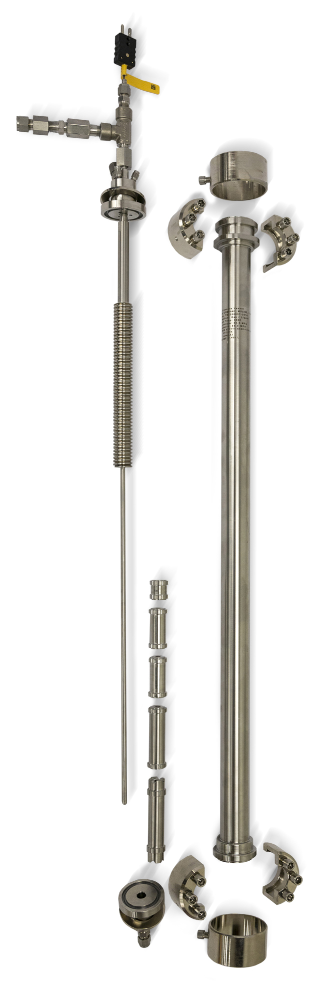
Tubular reactors may be empty for homogenous reactions or packed with catalyst or other solid particles for heterogeneous reactions. Packed reactors require upper and lower supports to hold particles in place. Upstream packing often includes inert material to serve as a pre-heat section. Pre-heating can also be done with the Parr internal spiral preheater which keeps incoming reagents close to the heated wall during entry.
It is often desirable to size a tubular reactor to be large enough to fit 8 to 10 catalyst particles across the diameter or annular gap and at least 5 reactor diameters in length.
Tubular reactor systems are highly customizable and can be made to various lengths and diameters and engineered for various pressures, temperatures and materials of construction.
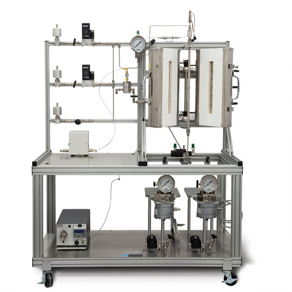
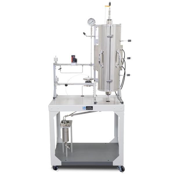
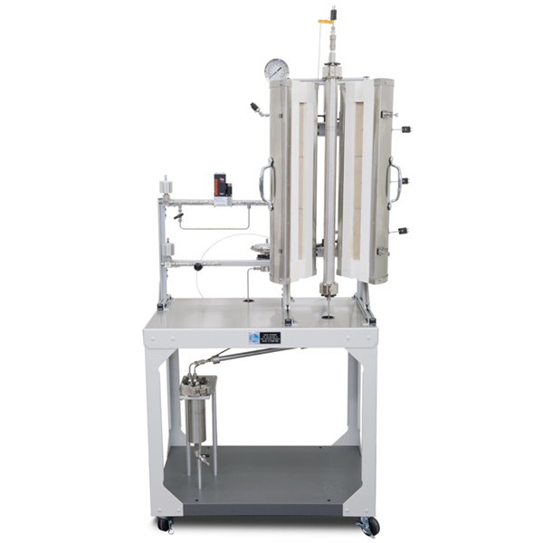
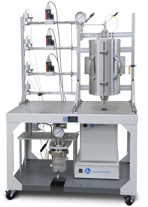
Tubular reactors can have a single wall and be heated with an external electric furnace or they can be jacketed for heating or cooling with a circulating heat transfer fluid. External furnaces are typically rigid, split-tube heaters. Insulation is provided at each end, to minimize heat loss and prevent the end closures from being heated. The heater length is normally divided into one or three separate heating zones, although it can be split into more zones if required.
We can furnish either a fixed internal thermocouple in each zone or a single moveable thermocouple in a center line thermowell that can be used to measure the temperature at points along the catalyst bed. External thermocouples are typically provided for control of each zone of the heater, as can be seen in the ‘Open 3-Zone Split Tube Furnace” photo.
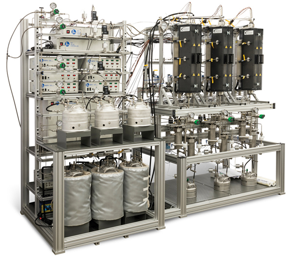
Gas Feed Systems
Various gas feeds can be set up and operated from a gas distribution rack. In order to deliver a steady flow of gas to a reactor, it is necessary to provide gas at a constant pressure to an electronic Mass Flow Controller. This instrument will compare the actual flow rate delivered to the set point chosen by the user, and automatically adjust an integral control valve to assure a constant flow. Care must be taken to size these controllers for the specific gas, flow rate range and maximum pressure of operation. A mass flow controller needs a power supply and read-out device, as well as a means of introducing the desired set point.
When ordering mass flow controllers, you will need to specify:
1. Type of gas to be metered (e.g. N2, H2, CH4, etc.)
2. Maximum operating pressure of the gas (14, 100, 200 or 300 bar)
3. Maximum flow rate range in standard cc’s per minute (sccm)
4. Pressure for calibration of the instrument
Mass flow controllers are available for use to 100 bar or to 300 bar. Considerable savings can be obtained if the mass flow controller is to be used only to 100 bar.
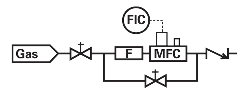
The schematic above depicts the installation of a mass flow controller for the introduction of gas to a continuous-flow reaction system. Such installations are enhanced with the addition of a by-pass valve for rapid filling or flushing.
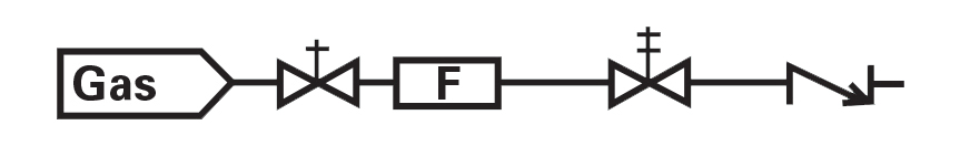
A purge line can also be added. It is typically used for feeding nitrogen or helium to remove air before operation or to remove reactive gases before opening the reactor at the end of a run. The purge line includes a shut-off valve, filter, metering valve, and a reverse-flow check valve.
Shut-off valves can be automated when using a 4871 Control system or 4880 Touchscreen Controller for 5420 model Tubular Reactors.
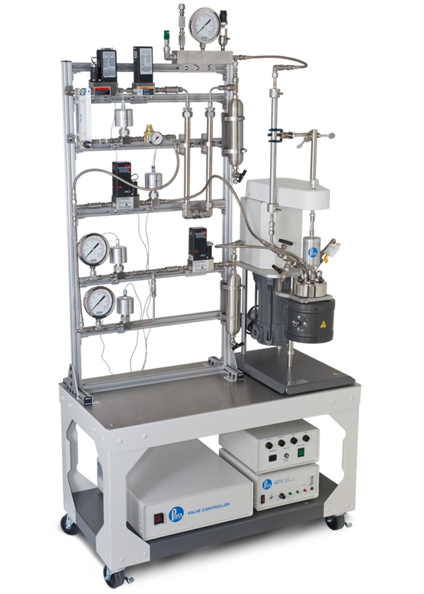
Liquid Metering Pumps
High pressure piston pumps are most often used to inject liquids into a pressurized reactor operating in continuous-flow mode. For low flow rates, HPLC pumps, many of which are rated for 150-400 bar, are excellent choices.
Typical flow rates for pumps of this type include 0.01-4.0 mL/minute, 0.1-20 mL/minute, and 1.0-40 mL/minute. Pumps are available to accommodate manual flow rate control from their digital faceplate or computer-control from a 4871 Process Controller.
Parr can assist with the feed pump selection. We will need to know the type of liquid; the minimum, typical, and maximum desired feed rate; the maximum operating pressure; and any special operating considerations such as explosion proof operation or corrosion possibilities.
Cooling Condensers
Cooling condensers are available to cool the reaction products. An adaptation of our standard condensers provide an excellent design.
Back Pressure Regulators
The reactor pressure is maintained by a Back Pressure Regulator (BPR) installed downstream of the reactor. This style of regulator will release products only when the reactor pressure exceeds a preset value by the operator.
When a BPR is used in conjunction with mass flow controllers, the user can maintain a constant flow of gas through a reactor held at elevated constant pressure. This provides for the highest degree of control and reproducibility in a continuous-flow reactor system.
An alternate BPR is also available to permit pressure let-down of a two-phase stream from the reactor. This BPR requires that the operator provide a source of nitrogen or air at a pressure slightly above the desired operating pressure. With this style of BPR, the high-pressure gas/liquid separator can be replaced with a low-pressure liquid product receiver.
Gas/Liquid Separators
Tubular reactors operating in continuous-flow mode with both gas and liquid products will typically require a Gas/Liquid Separator. The separator is placed downstream of the reactor, often separated from the reactor by a cooling condenser. In the separator vessel, liquids are condensed and collected in the bottom of the vessel. Gases and non-condensed vapors are allowed to leave the top of the vessel and pass to the back pressure regulator. It is important to operate the standard BPR with a single fluid phase to prevent oscillation of the reactor pressure.
The Gas/Liquid Separator can be sized large enough to act as a liquid product receiver that is drained periodically. Many of the non-stirred pressure vessels made by Parr are ideally suited for use as Gas/Liquid Separators. Vessels of 300, 600, 1000, or 2000 mL are commonly chosen. Upon request, the bottom of the separator can be tapered to facilitate draining and/or automatic liquid drain capability can be added.
Solids Hopper
Solids hoppers are available which are designed for addition of bulk solids such as catalysts or reactants (i.e. biomass) to a reactor at temperature and pressure. In many applications semi-batch addition of bulk solids into a hot fluid bed, stirred, or other reactor is desired. Parr offers several sizes, including 0.4 L and 1.3 L solids hopper vessels for semi-batch addition of solids at temperature and pressure.
Continuous Bulk-Solids Feeder
Parr’s new laboratory-scale automated solids-feed module is designed to continuously deliver free-flowing non-cohesive bulk solids into specially customized Parr continuous stirred, tubular, or fluidized bed reactors.
Control and Data Acquisition Systems
There are three options for control of Parr continuous reactor systems:
- Model 4871 Process Logic Controller (PC controlled) enables data logging of process data, programmable safety interlocks, programmable automation, and remote operation (via PC). Automatable features offered include automated pressure control (with ramping capability), automated liquid draining, automated setting of reactant flow rates, automated shutoff valves, and automated sampling. Pre-programmed profiles enable highly reproducible automated test runs. Other features available with the 4871 Process Controller include external vaporization/preheating, differential pressure measurement, physical E-stop button, and analog or digital communication with instruments such as gas monitors and ventilation flow monitors.
- Model 4880 3-zone Tubular Touchscreen Controller is also available for use with 5420 series configurable entry level tubular reactor systems with automated shutoff valves, safety interlocks, and data logging. This controller mounts on the reactor flow stand, is not upgradeable, and is designed for use with up to four gas feeds and two liquid feeds.
- Model 4848 Reactor Controller (Local Control System) is also available, but limited to control of a single reactor heated zone and monitoring of pressure and temperature. It is not able to control or interlock reactant feeds or interlock more than one heated zone.